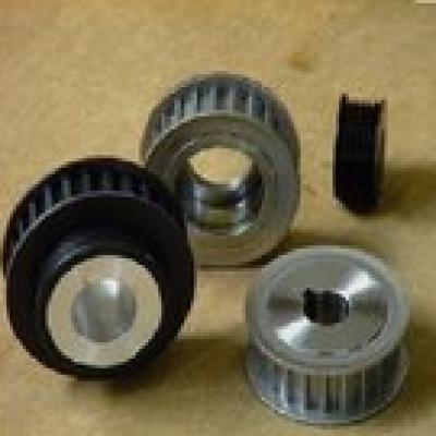
Sprocket design and processing

1, ISO Sprocket design: for the pitch of 12.7-38.1 standard chain sprocket manufacturers have adopted
Standard hobs are produced on hobbing machines. When processing, the user only needs to provide the number of sprocket teeth, pitch and roller diameter to produce. The sprocket design is designed according to GBl244-85. On the basis of the user providing the necessary data, the non-standard sprocket should be calculated as follows: the diameter of the index circle: d = P / sin 180 degrees / Z = P · K, P - pitch, K - tooth coefficient can be checked.
Rim radius: Rmin=O.505d, d=roller diameter. pressure angle? Qmin = l20 degrees - 90/2; Qmax = 140 degrees - 90/2. Generally choose Qmax. Tooth surface arc radius Remin=O.008d; (Z·Z+180); Remax=O.12(Z·Z+2). Remax is generally used. The position Do of the radius of the tooth surface arc is on a circumference of d 0.2p. The amount of separation of the groove S: machine addition, Smin=0.08d; non-addition, Smin=O.04P. Generally, the machine is used to add the amount of separation of the grooves. The pitch angle a = 360 / Z. Tooth thickness: The single row is 0.95 in the inner section and the double row is 0.93 in the inner section.
The tip circle can be determined according to the drawing, and a roller diameter of 0.85 to 0.95 times can be added on the basis of the index circle. The above data is an important parameter for sprocket design.
of course. The sprocket design of the special chain differs from this and needs to be calculated according to the sprocket formula of the relevant manual.
2, the most important part of the sprocket tooth processing sprocket processing is the tooth shape processing. As mentioned above, the sprocket of the standard chain is mostly machined on a hobbing machine with a hob. The processing methods of large-size and non-standard sprocket are different depending on the equipment, the number of tools and the number of processing methods. At present, the most widely used is still the forming method of milling and sprocket and the Fancheng method of rolling sprocket. The tooth profile of the Roller Chain sprocket cutter is designed according to the shape of the sprocket. In order to save the tool, the tool is usually grouped according to the number of sprocket teeth. Each group is designed according to the calculated number of teeth. The number of teeth can be calculated as follows:
Zc=2Zl·Z2/Zl+Z2 where: Zl has the smallest number of teeth in the same group, and Z2 has the largest number of teeth in the same group. (1) Forming knife processing tooth shape method: It is a commonly used processing method to form a tooth groove on a horizontal or vertical milling machine equipped with an indexing head by using a forming disc milling cutter or a finger forming milling cutter. Suitable for batch processing of large pitch sprocket. (2) Saddle-shaped milling cutter machining method: using a saddle-shaped milling cutter on a horizontal milling machine equipped with an indexing head while milling two symmetrical teeth on two adjacent slots is the current toothed sprocket Commonly used processing method. Suitable for medium and small batch production. (3) Rolling and cutting tooth form method: The tooth groove is machined by the hob on the Gear hobbing machine, which is suitable for the ANSI Sprocket machining with the standard sprocket pitch P=38.1 or less. high productivity. Good precision. (4) Tooling method of tooth shaping: The sprocket tooth groove is machined on the gear shaping machine by a disc cutter or a comb cutter. Suitable for single-piece small batch production. (5) Larger sprocket can also be used for scribing, drilling, or machining. It is obviously a method of processing. Obviously, this method is backward, but the large sprocket is limited by processing equipment and quantity. This method can also be used. (6) Recently, some units have solved the problem of large Finished Bore Sprocket processing by using the profiling machine to cut the tooth shape, which is very creative.
The profiling tooth profile processing process is as follows:
A. First place the sprocket added to the indexing plate, and the sprocket is fixed by the pressure plate and the bolt on the mandrel. The ring gear surface must be flat.
B. Cut the tooth profile of the sample tooth shape at a position less than the design tooth shape by 4-5 mm at any position on the machined ring gear, and then measure the perpendicularity of the ruler surface with a square ruler.
C. Measure the distance H between the cut depth of the cut and the edge of the wellbore that has been machined.
D. The calculation also requires processing depth B. B = measurement size - the distance between the edge of the shaft hole and the edge of the graduation circle diameter.
E. Adjust the cutter link size, that is, extend a depth based on the original size, and then cut it according to the sample.
F. After cutting a tooth, use the indexing plate to index. After cutting three teeth, the same side distance is measured across the teeth. After cutting the fourth tooth, move the same side to the same position in the same way, and so on.
G. If the difference between the measured dimensions is large or the width of the crest is large, the wider side can be more than partially cut and welded to the other tooth surface for trimming.
H. The toothed surface after cutting is surface-hardened by grinding with a hand wheel.
L. Perform other processing.
3. Slice type, flange type chain runner adding method
(1) Sheet sprocket processing: The sheet sprocket is generally machined after cutting with steel plates to improve the material utilization rate. Most of the small-sized sprocket wheels, the standard sprocket is the majority, after machining, it is processed on the hobbing machine, and several pieces can be processed at one time.
(2) Flanged sprocket processing: flanged sprocket processing has the following two methods;
A. Overall processing, that is, machining the tooth shape after cutting with a bar material. This method has low material utilization rate and high cost.
B. Welding processing, it is obvious that the material utilization rate of this method is higher than the overall processing and the wood is low. The specific processing method is as follows: the ring gear portion can be roughened by the steel plate and the outer diameter and the shaft hole are cut, and the weld hole is left on the side of the shaft hole. Then, the flange portion of the bar material is formed into a convex shape, and the ring gear portion and the flange portion are joined together and then double-sided welded to process the finished product, and the welded portion is partially arc-shaped. After the machine is added, an appropriate method is selected to process the tooth profile.
The welding rod of the welded sprocket is preferably a low-hydrogen welding rod to prevent the 45 steel from cracking due to the welding joint. For large important sprocket welding, the electrode is preferably preheated, preheating temperature 150-200, time 1-2 hours.
