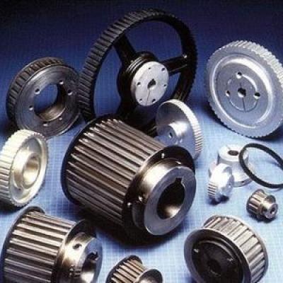
Sprocket application and structural design

Application of sprocket: widely used in mechanical transmission of chemical, textile machinery, food processing, instrumentation, petroleum and other industries
Finished Bore Sprocket parameter calculation formula:
Index circle diameter: d=p/sin180°/z p=pitch can be checked table z=number of teeth
Tip circle (outer diameter): D = p × (0.54 + cot180 ° / z)
Give you the usual sprocket pitch, calculate it yourself, don't understand, ask me again.
3/8=9.525 1/2=12.7 5/8=15.875 3/4=19.05
3 points 4 points 5 points 6 points
Index circle diameter: d=p/sin(180°/z)
Tip circle diameter: dmax=d+1.25p-d1
Dmin=d+(1-1.6/z)p-d1
Root diameter: df=d-d1
Note: p chain pitch
z sprocket number
D1 chain roller diameter
Sprocket model: Contains non-standard sprocket (customized according to customer drawings), standard sprocket (American standard and metric).
Common materials for sprocket: C45
Common processing methods for sprocket: quenching treatment, blackening of the surface.
General principles for the selection of the number of sprocket teeth:
19 teeth or more
It is generally used for driving Taper lock Sprocket running at medium and high speed and normal working conditions.
17 teeth
Only for small pitch drive sprocket.
23 teeth or more than 23 teeth
Recommended for use in situations where there is an impact. When the speed ratio is low, the high-numbered sprocket can greatly reduce the amount of rotation of the i-link, the tensile load of the chain, and the load of the bearing.
Structural design of roller Stock Sprocket
Tooth shape of the sprocket
The sprocket tooth shape must ensure that the chain can smoothly and freely enter and exit the mesh, minimize the impact and contact stress of the link during the meshing, and be easy to process.
The commonly used sprocket face tooth profile is shown in Figure 1. It is composed of three arcs aa, ab, cd and a straight line bc, referred to as a three arc-linear tooth shape. The tooth profile is machined with a standard tool. It is not necessary to draw the face tooth shape on the sprocket work diagram. Just indicate "the tooth shape is manufactured according to 3RGB1244-85" on the drawing, but the axial tooth profile of the sprocket should be drawn. See Figure 2 for dimensions and refer to the relevant design manual. Parameter calculations have been mentioned before, no repetitive narrative!
2. Sprocket structure
Figure 3 shows four commonly used sprocket structures. The small-diameter sprocket is generally made in one piece (Fig. 3a). The medium-diameter WELD-ON Sprocket is mostly made of a web. For easy handling, loading and weight reduction, the hole is opened on the web (Fig. 3b). The large diameter sprocket can be used. Made in combination (Fig. 3d), the ring Gear and the wheel core can be made of different materials! For example, C45, stainless steel and other materials.
3. Sprocket material
The sprocket material should ensure that the gear teeth have sufficient strength and wear resistance, so the sprocket tooth surface is generally heat treated to achieve a certain hardnes

